This is a tubed astable multivibrator, each half of which drives the cathode bias of a miniature pentode in a primative VCA configuration; which results in an output alternating between two inputs.
Originally, electronic switches were an inexpensive option to the dual trace oscilloscope preamp, in the era that a proper dual trace o-scope would compete with a new car in cost. Heathkit and Eico, both being manufacturers who offered test equipment kits for the DIY minded individual, offered these up as a low budget method to comparing input vs. output in a real-time manner.
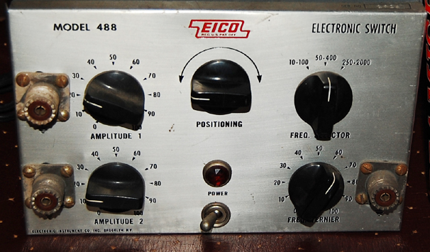
Naturally Heathkit and Eico were not the only companies making these things, but the bulk of what you're likely to come across will be the Heathkit S-2, S-3 and the Eico 488. While similar in function they differ in method, and some of what follows is not universal to the class of instrument.
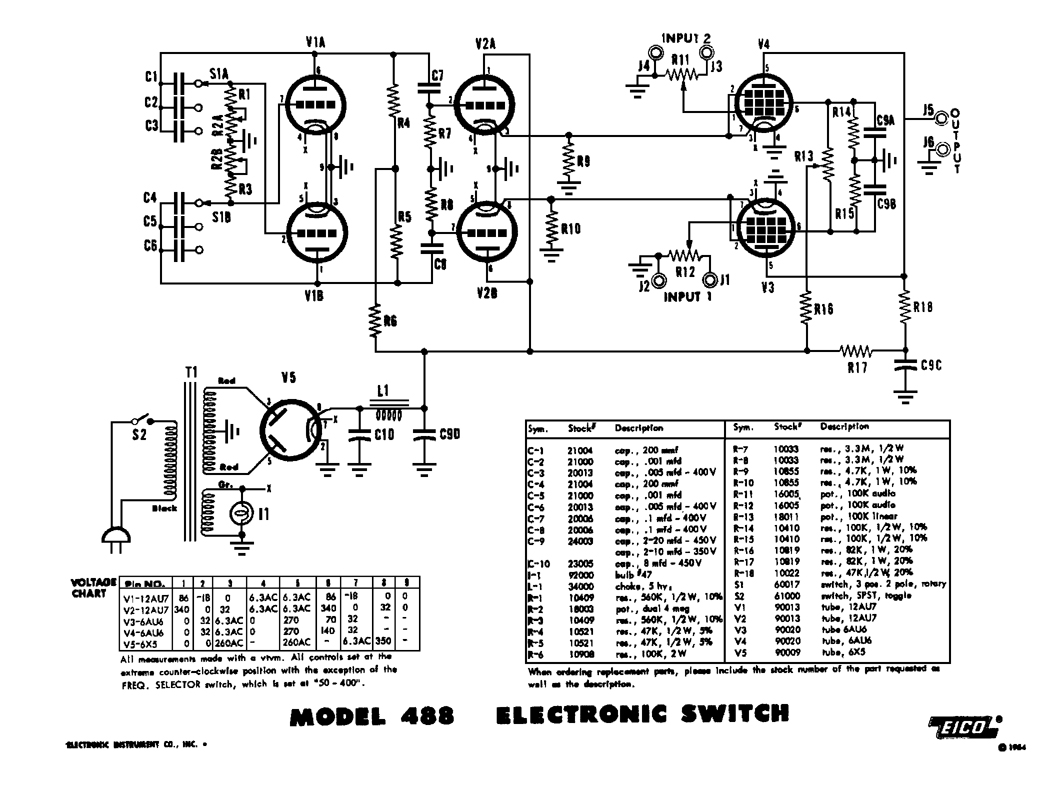
click for size.
Musically speaking, an electronic switch can act like a hard tremolo when only one input is used, and with both inputs driven at higher switching rates it delivers an effect not entirely unlike ring modulation. The baselines of the input sections are somewhat adjustable, so the unit can also output a square wave without any signal input.
There are, however, points that need to be addressed prior to using this in an audio configuration. Referring to the upper right area of the schematic we can see the output jack directly coupled with the plates of the pentodes. According to the voltage chart, pin 5 of V3 and V4 have 270 volts on them; which of course means that the signal leg of the output jack on an unmodified unit will also carry 270 volts DC.
270 volts DC will make short work in obliterating most audio circuits out there, and can also make short work of your bowels should you happen to connect with it yourself.
The easiest modification here is to drop a blocking cap on the output. Simply select a 400 or better volt cap of sufficient size (research tube audio amplifier coupling caps if you're in the dark as to what constitutes sufficient) I used a 0.47 uf. The cap should be wired such that it blocks as opposed to smoothes DC; if that is not immediately understood it is highly advisable to seek assistance in this endeavor.
I intend on researching benefits of placing an audio interstage or output transformer in lieu of the blocking cap, though space and expense are two factors to consider.
Mitigating switching thump. The positioning knob acts as a bias balance between signal amplifier stages, which would place the zero line at different elevations on the oscilloscope screen (and delivers our square wave feature). Switching thump diminishes as the DC potential between stages decreases, though I haven't come close to eliminating it. This has not been bothersome to me yet as my 488 sees most all of its action in electronic oscillator drone work, but I will look into eliminating it entirely for a future installation.
Another future modification I am looking into entails patching in an external sync, as the stock range of switching speeds is limited in scope and tied to manual controls.